

ASSEMBLY & TEST
After the A.T.E. interface board has been manufactured, the specific electronic components must be attached to form a functional printed circuit assembly (sometimes called a “printed circuit board assembly” or PCBA).
 There are probably a mixed variety of components to be assembled, some requiring leads to be inserted into through-holes and some to be mounted on the surface. In surface-mount (SMT – surface mount technology) construction, after applying a solder paste, the components are placed on the pads or lands on the outer surfaces of the PCB. In both kinds of construction, component leads are electrically and mechanically fixed to the interface board with a molten metal solder, usually facilitated by some form of reflow. There are a variety of soldering techniques used to attach components to an interface board.
Often, through-hole and surface-mount construction must be combined in a single assembly because some required components are available only in surface-mount packages, while others are available only in through-hole packages. Another reason to use both methods is that through-hole mounting can provide needed strength for components likely to endure physical stress, while components that are expected to go untouched will take up less space using surface-mount techniques.
After the board has been populated it may be tested in a variety of ways: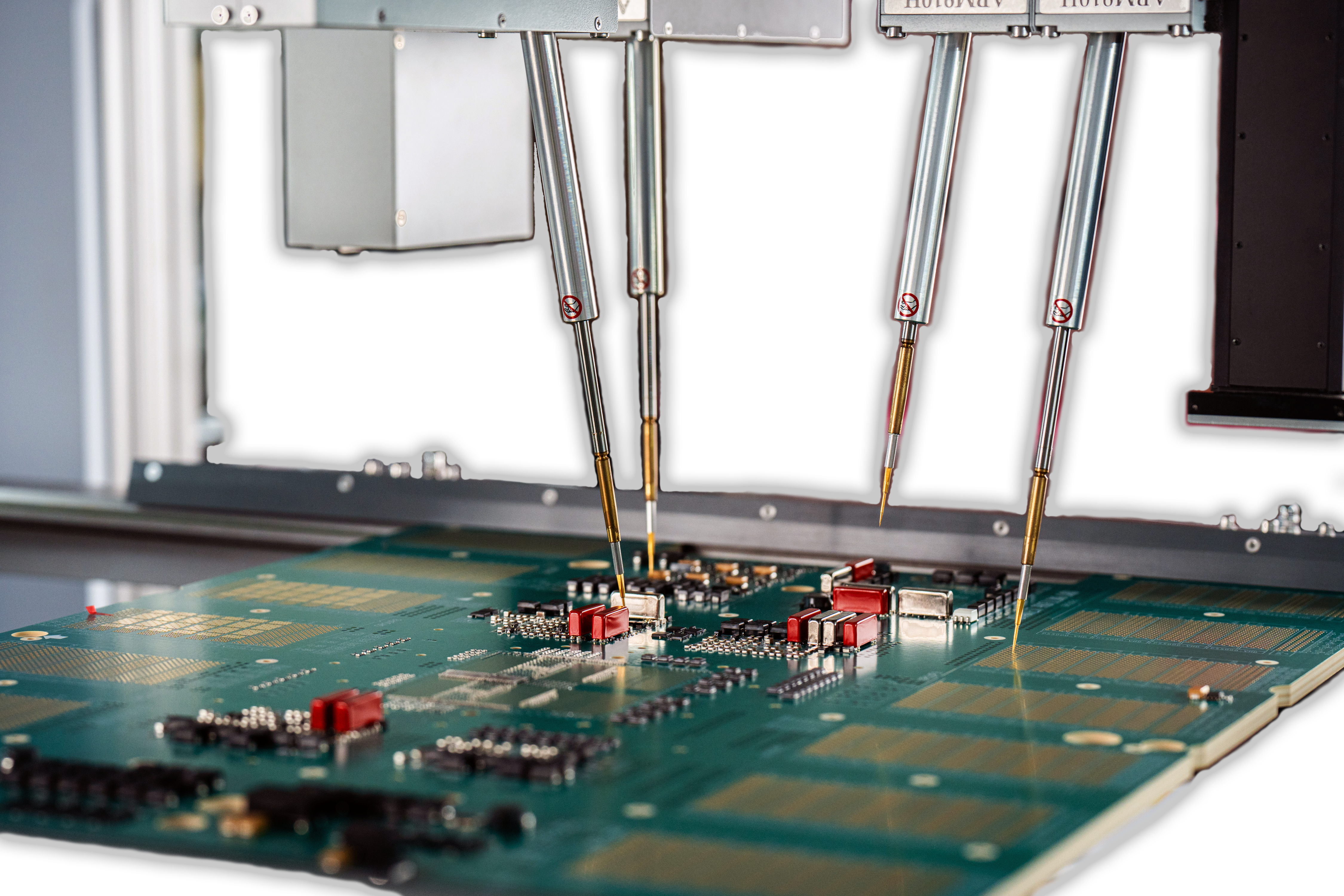
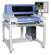
While the power is off, a visual inspection, usually by means of an automated optical inspection (or A.O.I.) may be performed. JEDEC guidelines are followed for PCBA component placement, soldering, and inspection are commonly used to maintain quality control in this stage of interface board assembly. This visual test includes the presence or absence of components, proper orientation, tomb-stoning and the quality of the solder connections.
An additional test may also be employed to test the board and the components electrically, through the entire network. For this, R&D Altanova employs their Interceptor Test systems. This does two things; it verifies that the net is functioning as planned, designed and intended and it creates a signature of that board and net, so that in the future, if there is any damage to the interface board and repair is performed, there is a way to ensure that the net is restored to its original electrical performance level.